SiK Telemetry Radio
FCC ID Disclaimer: This is only a product for evaluation, testing and development. Please, expand for more information.
Please note, 3DR SiK Telemetry Radio from 3DR, Inc or Mayan Robotics LLC do not possess an FCC ID. These kits are designed to allow:
Product developers to evaluate electronic components, circuitry, or software associated with the kit to determine whether to incorporate such items in a finished product, and
Software developers write software applications for use with the end product. It is designed to be used by product developers, software developers, and system integrators for assessing electronic components, circuitry, or software associated with the kit.
The assembled kits may not be resold or marketed unless all necessary FCC equipment authorizations have been obtained.
Users accept full responsibility for ensuring compliance with any applicable FCC regulations or authorizations should they choose to use this kit for further development or integration purposes.

This is an Original 3DR SiK Telemetry Radio. It is a small, light and inexpensive open source radio platform that typically allows ranges of better than 300m “out of the box” (the range can be extended to several kilometers with the use of a patch antenna on the ground).
Based on SI1060-A-GM from Silicon Labs, this radio uses open source firmware which has been specially designed to work well with MAVLink packets and to be integrated with the Mission Planner, Copter, Rover and Plane firmware.
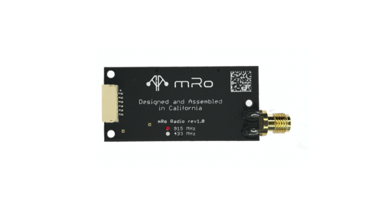
This radio works on 915Mhz and you should purchase the model if it is appropriate for your country/region.
Purchase
Quick Start
Section titled “Quick Start”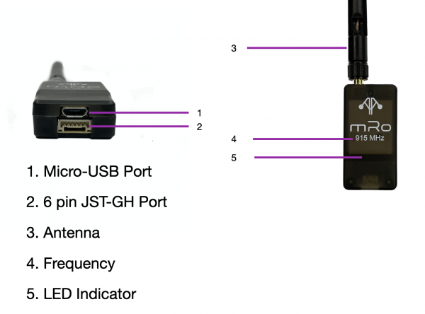
Specifications
Section titled “Specifications”| Specifications | 3DR SiK Telemetry Radio |
|---|---|
| Receiver sensitivity | |
| Transmit power | up to 20dBm (100mW) |
| Air Data transfer rates | |
| Dimensions | 55.7mm x 25.7mm x 13mm |
| Weight | 14.3g (0.50 oz)/22.24g (0.78 oz) with antenna |
Status LEDs
Section titled “Status LEDs”The radios have 2 status LEDs, one red and one green. The meaning of the different LED states is:
- Green LED blinking – searching for another radio
- Green LED solid – link is established with another radio
- Red LED flashing – transmitting data
- Red LED solid – in firmware update mode
Connecting the radios
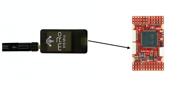
Section titled “Connecting the radios”The radio has interchangeable air and ground modules, meaning that you use them as a pair but it does not matter which one goes on the vehicle and which remains on the ground.
The radio has a micro-USB port, and a JST-GH six-position port. The following sections explain how to connect these to autopilots and ground stations.
Pinout
Section titled “Pinout”| Pin (wire color) | Signal – Flight Controller Perspective (Direction) | Signal Radio Perspective (Direction) | Volt |
|---|---|---|---|
| 1 (red) | VCC | VCC | +5V |
| 2 (black) | TX (OUTPUT) | RX (INPUT) | +3.3V |
| 3 (black) | RX (INPUT) | TX (OUTPUT) | +3.3V |
| 4 (black) | CTS (INPUT) | RTS (OUTPUT) | +3.3V |
| 5 (black) | RTS (OUTPUT) | CTS (INPUT) | +3.3V |
| 6 (black) | GROUND | GROUND | GND |
Features
Section titled “Features”- MAVLink protocol framing and status reporting
- Frequency hopping spread spectrum (FHSS)
- Adaptive time division multiplexing (TDM)
- Support for LBT and AFA
- Configurable duty cycle
- Built-in error correcting code (can correct up to 25% data bit errors)
- Demonstrated range of several kilometres with a small omni antenna
- Can be used with a bi-directional amplifier for even more range
- Open source firmware
- AT commands for radio configuration
- RT commands for remote radio configuration