Radio 2
The 3DR Radio 2 is a professional, cost-effective connectivity bridge developed and manufactured by 3DR, in collaboration with Nimbus Robotics AI. It enables HaLow (Wi-Fi IEEE 802.11ah standard) connectivity for drones and robotics applications. Operating in the Sub-1 GHz band, 3DR Radio 2 offers long-range communication, low power consumption, and strong signal penetration, making it ideal for industrial, UAS, energy, and robotic applications. It features an RF switch and an integrated Power Amplifier (PA) in the SoC, delivering up to 23 ± 2 dBm output power.
Key Features
Section titled “Key Features”- Compact design: Convenient for a wide range of applications
- Versatile Interfaces: USB, Serial, Ethernet, Digital & Analog, Raspberry Pi 40-pin Header(PLUS only)
- Seamless Communication: Incorporates the MQTT protocol to integrate all interfaces with HaLow wireless functionality
- Networking Modes:
- Access point (AP) / Station (STA)
- Mesh networking capabilities
- Transceiver performance: Operates efficiently in the Sub-1GHz ISM band with low power and long-range functionality. Achieves a receive sensitivity of -107 dBm at MCS10
- RF Optimization: Tuned RF interface at 50 ohms
- FCC-certified: Certified output power of up to 23 +/- 2 dBm
The 3DR Radio 2 is a high-performance, long-range module designed to serve as a wireless HaLow inter-connectivity bridge. It offers a wide range of connectivity options, making it ideal for integrating any Industrial IoT application with Wi-Fi HaLow. The device can be powered either through a USB connection or via the +5V and GND pins using any Telemetry port connector.
Purchase
The 3DR Radio 2 Series consists of four distinct products—CORE, STATION, ACCESS, and PLUS—each designed to suit a range of application needs from compact embedded modules to fully integrated connectivity hubs for industrial and robotics deployments.
3DR Radio 2 Series product comparison
Section titled “3DR Radio 2 Series product comparison”| Series | CORE | STATION | ACCESS | PLUS |
|---|---|---|---|---|
| Launch Date | November 2025 | November 2025 | October 2025 | December 2025 |
| PCB Dimension (mm) | 18 x 14 x 3 | 20 x 30 x 5 | 33 x 39 x 12 | 65 x 55 x 20 |
| Telemetry Port | Yes | Yes | Yes | |
| Secondary Port | Yes | Yes | Yes | |
| USB-C/Debug Port | Yes | Yes | ||
| Ethernet Port | Yes | Yes | ||
| Raspberry Pi 40-pin Header | Yes | |||
| Weight (g) | 5 | 10 | 25 | 50 |
| Assembled PCB | 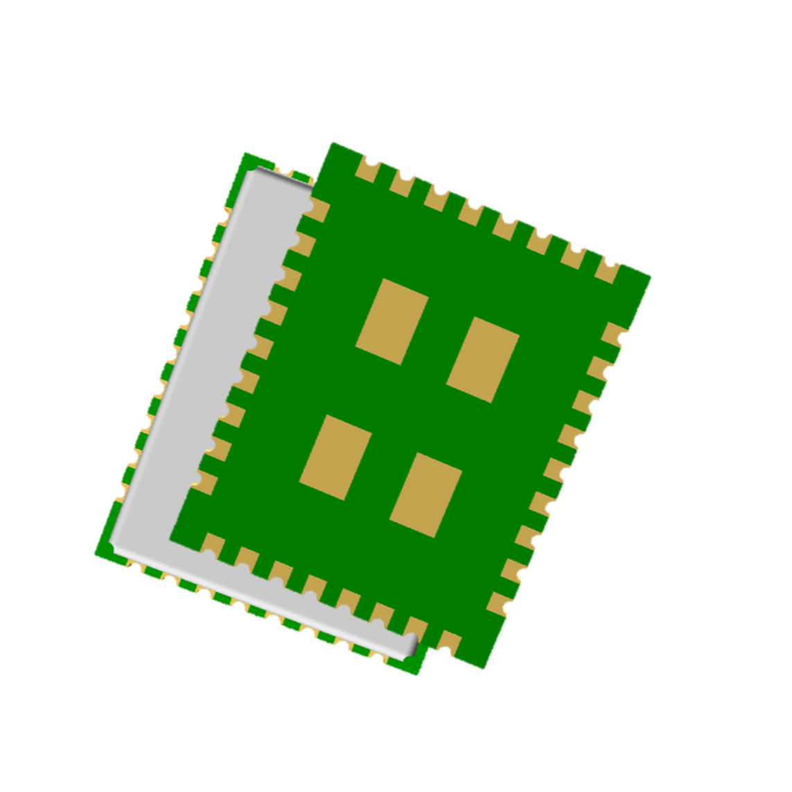 | 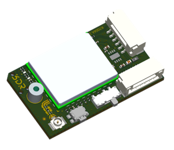 | 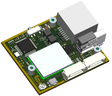 | 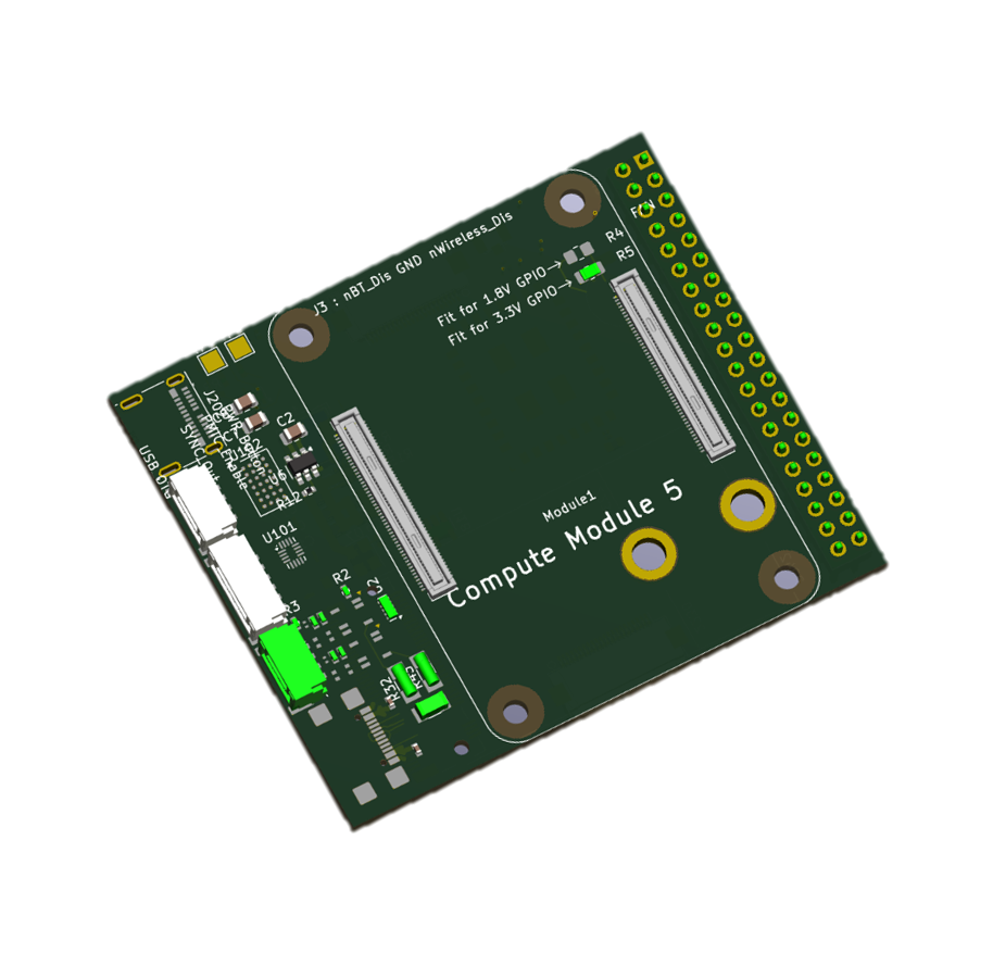 |
3D View
Section titled “3D View”3DR Radio 2 CORE - R7007 
Section titled “3DR Radio 2 CORE - R7007 ”Reflowable Module
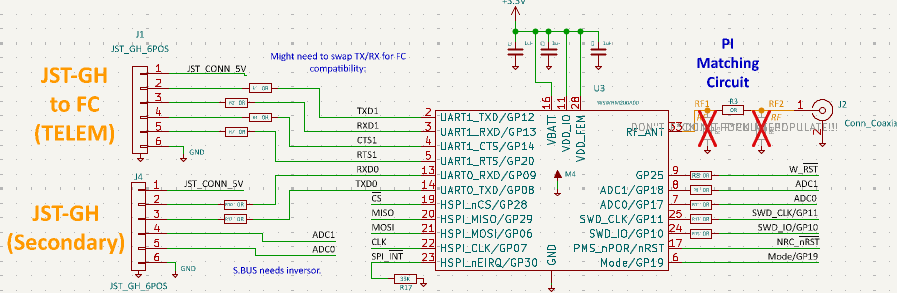
Typical Circuit
3D Diagram .STP file
3DR Radio 2 STATION - R7004
Section titled “3DR Radio 2 STATION - R7004 ”- Assembled Module: Engineered for use as a STATION in scenarios where compact size and low weight are critical, including drones, robots, and edge or node devices.
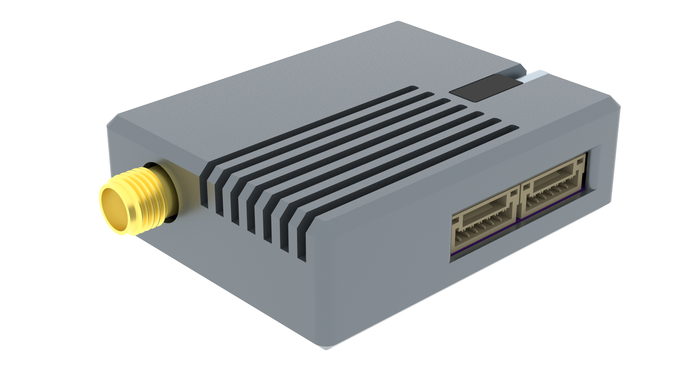
3DR Radio 2 ACCESS - R7002 
Section titled “3DR Radio 2 ACCESS - R7002 ”- Assembled Module: Optimized for integration into ground stations, typically serving as Access Points.
3DR Radio 2 PLUS - R7006
Section titled “3DR Radio 2 PLUS - R7006 ”- Assembled Module: Designed for seamless integration into applications requiring onboard processing, leveraging the on board Raspberry Pi Compute Module 5.
Specifications
Section titled “Specifications”Mechanical
| Specification | Value |
|---|---|
| Dimensions | 44.5L x 35W x 13.8H mm |
| Weight | 25g |
Operational
| Specification | Min | Max | Unit |
|---|---|---|---|
| Storage | -40 | +125 | °C |
| Operation | -40 | +85 | °C |
| Voltage(VIO:3.3) | 3.6 | 5.5 | V |
| Current(VIO:3.3) | 150 | 220 | mA |
Power draw - RF Only
| Radio Output Setting | Current (mA) | Power (mW) |
|---|---|---|
| TX @ 0 dBm | 205 | 677 |
| TX @ 10 dBm | 241 | 795 |
| TX @ 15 dBm | 284 | 937 |
| TX @ 20 dBm | 421 | 1389 |
| TX @ 25 dBm | 614 | 2026 |
| Continuous Rx @ -85 dBm | 27 | 89 |
Values are typical for radio module only and may vary depending on deployment and configuration.
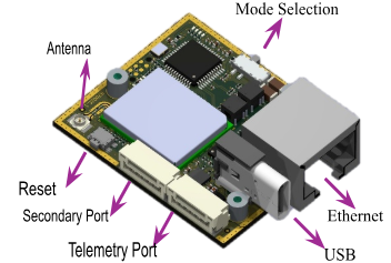
Module Interfaces
Section titled “Module Interfaces”Telemetry Port: Connected to application serial port (Drone, Robot etc…)
Secondary Port: | Serial | Digital(P2,P3) | Analog(P4,P5) |
USB-C Port: | Program | Debug |
Ethernet: UDP (Standalone) | TCP/IP using a Web Server
Raspberry Pi 40-pin Header: Standard Raspberry Pi (PLUS only)
Telemetry Port Type JST-GH 6-pin connector.
| Pin # | Description |
|---|---|
| 1 | +5V Power-in |
| 2 | U1RX |
| 3 | U1TX |
| 4 | U1RTS |
| 5 | U1CTS |
| 6 | GND |
- Secondary Port Type JST-GH 6-pin connector.
| Pin # | Description |
|---|---|
| 1 | +5V Power-in |
| 2 | U0TX | USB | IO0 |
| 3 | U0RX | USB | IO1 |
| 4 | ADC1 |
| 5 | ADC0 |
| 6 | GND |
RF Characteristics
Section titled “RF Characteristics”The following table indicates the data rates per MCS and BW level.
| BW | MCS | Modulation / Coding Rate | EVM Spec (dB) | Max Power (dB) | Sensitivity Typ (dB) | Data Rate (Mbps) | Distance (km) |
|---|---|---|---|---|---|---|---|
| 1 MHz | 10 | BPSK 1/2 rep. 2x | -4 | 28 | -106 | 0.15 | 26 |
| 1 MHz | 0 | BPSK 1/2 | -5 | 28 | -103 | 0.3 | 18 |
| 1 MHz | 1 | QPSK 1/2 | -10 | 28 | -102 | 0.6 | 16 |
| 1 MHz | 2 | QPSK 3/4 | -13 | 28 | -100 | 0.9 | 13 |
| 1 MHz | 3 | 16QAM 1/2 | -16 | 27 | -97 | 1.2 | 13 |
| 1 MHz | 4 | 16QAM 3/4 | -19 | 27 | -94 | 1.8 | 11 |
| 1 MHz | 5 | 64QAM 2/3 | -22 | 26 | -89 | 2.4 | 3 |
| 1 MHz | 6 | 64QAM 3/4 | -25 | 24 | -88 | 2.7 | 2 |
| 1 MHz | 7 | 64QAM 5/6 | -27 | 22 | -87 | 3.0 | 1.5 |
| 2 MHz | 0 | BPSK 1/2 | -5 | 28 | -100 | 0.65 | 13 |
| 2 MHz | 1 | QPSK 1/2 | -10 | 28 | -98 | 1.3 | 10 |
| 2 MHz | 2 | QPSK 3/4 | -13 | 28 | -96 | 1.95 | 8 |
| 2 MHz | 3 | 16QAM 1/2 | -16 | 27 | -93 | 2.6 | 5 |
| 2 MHz | 4 | 16QAM 3/4 | -19 | 26 | -90 | 3.9 | 3 |
| 2 MHz | 5 | 64QAM 2/3 | -22 | 25 | -86 | 5.2 | 1.3 |
| 2 MHz | 6 | 64QAM 3/4 | -25 | 24 | -83 | 5.85 | 1.1 |
| 2 MHz | 7 | 64QAM 5/6 | -27 | 24 | -82 | 6.5 | 1 |
| 4 MHz | 0 | BPSK 1/2 | -5 | 29 | -98 | 1.35 | 11.5 |
| 4 MHz | 1 | QPSK 1/2 | -10 | 29 | -95 | 2.7 | 13 |
| 4 MHz | 2 | QPSK 3/4 | -13 | 28 | -93 | 4.05 | 11 |
| 4 MHz | 3 | 16QAM 1/2 | -16 | 27 | -90 | 5.4 | 3.5 |
| 4 MHz | 4 | 16QAM 3/4 | -19 | 27 | -87 | 6.1 | 2.5 |
| 4 MHz | 5 | 64QAM 2/3 | -22 | 26 | -83 | 10.8 | 1.5 |
| 4 MHz | 6 | 64QAM 3/4 | -25 | 25 | -81 | 12.2 | 1 |
| 4 MHz | 7 | 64QAM 5/6 | -27 | 25 | -80 | 13.5 | 0.9 |
Values are typical and may vary depending on deployment environment.
FCC Regulation for USA (23dBm +/- 2dB)
Section titled “FCC Regulation for USA (23dBm +/- 2dB)”| BW (MHz) | Usable Frequency (MHz) |
|---|---|
| 1 | 902.5, 903.5, 904.5, 905.5, 906.5, 907.5, 908.5, 909.5, 910.5, 911.5, 912.5, 913.5, 914.5, 915.5, 916.5, 917.5, 918.5, 919.5, 920.5, 921.5, 922.5, 923.5, 924.5, 925.5, 926.5 |
| 2 | 905.0, 907.0, 909.0, 911.0, 913.0, 915.0, 917.0, 919.0, 921.0, 923.0, 925.0 |
| 4 | 906.0, 910.0, 914.0, 918.0, 922.0 |
Network Topologies
Section titled “Network Topologies”AP, STAs Paired Connection
Section titled “AP, STAs Paired Connection”The device mode is set between STA and AP by updating the device using the UI configuration. The firmware can be updated either using the USB port or via the web server. The web server also provides configuration parameters to customize AP/STA nodes.
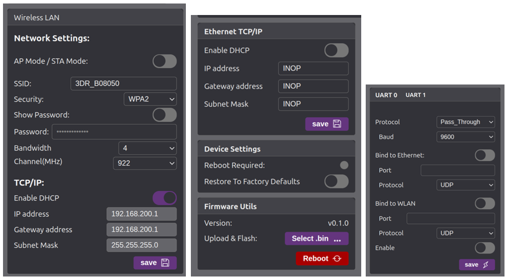
Configuration
Section titled “Configuration”The 3DR Radio 2 module includes a lightweight web server for intuitive configuration and OTA (Over-the-Air) firmware updates. It utilizes the MQTT protocol to interface with a wide range of physical connections, including Serial, USB, Ethernet, Digital I/O, and Analog inputs, creating an efficient wireless bridge over Wi-Fi HaLow.
On power-up, the module’s Access Point (AP) radio auto-assigns itself the IP address 192.168.200.1, and dynamically allocates IP addresses to connected Station (STA) devices. To ensure reliable access to the HaLow network and the embedded web server, it is recommended to manually configure the host computer’s Ethernet interface with the static IP address 192.168.200.250.
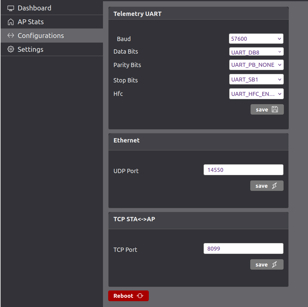
Configuration Parameters
Section titled “Configuration Parameters”| Setting | Description |
|---|---|
| Wi-Fi Mode | In AP mode, the device creates its own wireless network. In STA mode, it connects to an existing Wi-Fi network. |
| SSID | 3DR_xxxxxx The name of the Wi-Fi network broadcast (in AP mode) or the network to join (in STA mode). |
| Security | The Wi-Fi security type. Can typically be None, WPA2, etc. None means open network |
| Bandwidth | Bandwidth of the link, upto 4MHz BW supported |
| CH. Freq. | Sets the frequency channel for the 802.11ah (Wi-Fi HaLow) link. 925 MHz is common in US sub-GHz bands. |
| IP Address | Choose between Static or DHCP. If Static is selected, manual IP configuration is required. |
| Static IP | IP address assigned to the device when using static IP configuration. |
| Netmask | Subnet mask used to define the network’s address range. |
| Gateway | IP address of the router/gateway that routes packets outside the local subnet. |
| DHCP Server | When enabled, the device can act as a DHCP server (i.e., assign IPs to connected devices in AP mode). |
| Advanced | When checked, additional configuration options are likely revealed (e.g., TX power, beacon interval, etc.). |
| FW Update | Performs Firmware update over the Wi-Fi with the selected file and reboots the device. |
| Baud rate | UART0/UART 1 baudrate, default 115200 |
| UDP port | default UDP port 14551 |
Usage Guide
Section titled “Usage Guide”- Access Point (AP) Setup
The Access Point (AP) should be connected via the Ethernet port to local network or Ethernet port of the host computer. The host interface must be configured with the static IP address 192.168.200.250 and subnet mask 255.255.255.0, placing it within the 192.168.200.0 subnet. The USB interface on the AP serves a dual purpose: it can power the device and also be used to receive and display debug messages through a serial terminal application.
- Checklist AP
- Verify the Ethernet cable is securely connected and configure your network interface to use IPv4 address
192.168.200.250. - Use the USB-C connector to receive debug messages at a baud rate of 115200. If the module is not powered via USB-C, ensure it is powered through the Telemetry or Secondary Port.
You can access the device’s web interface by entering 192.168.200.1 into a web browser, allowing you to configure settings of AP.
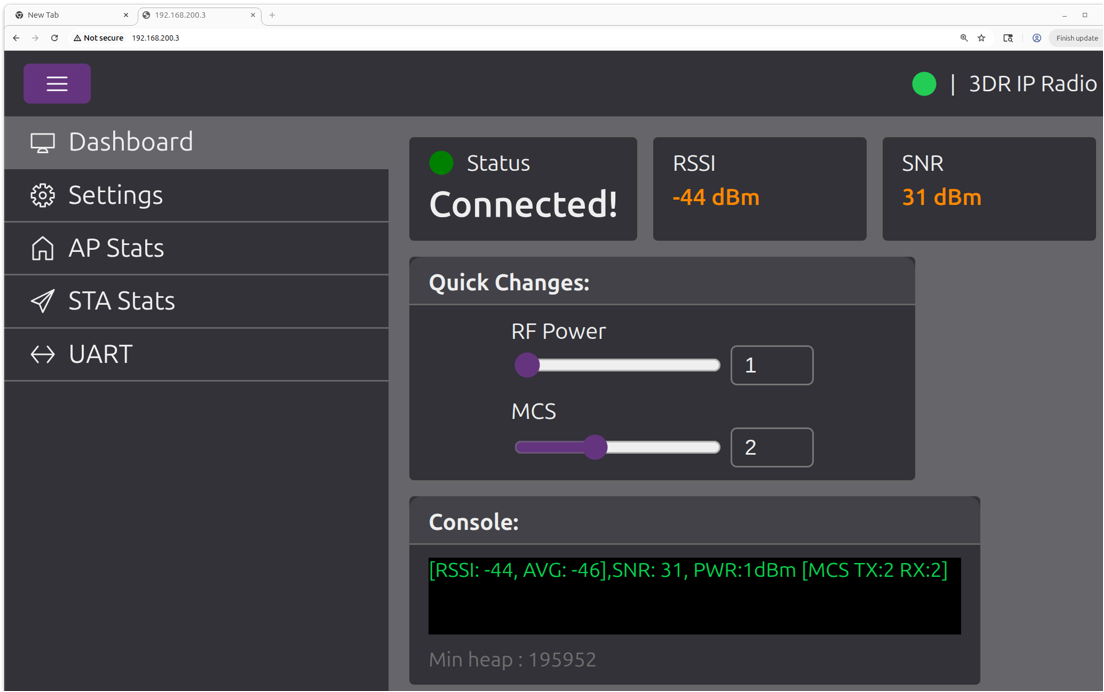
Station (STA) Setup
Section titled “Station (STA) Setup”One or more Station (STA) devices can automatically connect to the Access Point (AP) and will be assigned IP addresses within the 192.168.200.x subnet, as managed by the AP’s DHCP service. Each STA should be connected to the autopilot or robotic system via the Serial interface, using the 6-pin JST-GH port on the 3DR Radio 2 module.
- Checklist STA
- Connect the STA module to your autopilot using the Telemetry port for serial communication.
- Ensure the module is powered via USB-C or the Telemetry port.
- Confirm the correct wiring for U1TX, U1RX, +5V, and GND.
- Wait for the STA to automatically connect to the AP and receive an IP address.
You can access the STA’s web interface by entering its IP address (e.g., 192.168.200.3) into a web browser. The IP address assigned to each STA can be viewed via the AP’s USB debug port or through the Web interface.
UI Features
Section titled “UI Features”- MAVLink protocol support
- MQTT protocol integration
- Long-range Sub-1GHz operation
- Low power consumption
- Strong signal penetration
- FCC certified operation
- Web-based configuration interface
- OTA firmware updates
- Multiple connectivity options (USB, Serial, Ethernet, Digital I/O, Analog)
- Mesh networking capabilities
- Professional-grade reliability
User Guide
Section titled “User Guide”For a comprehensive setup guide, please refer to the 3DR Radio 2 Setup Guide.
Helpful Links
Section titled “Helpful Links”Version: 0.1.0 Last Updated: September 2025 Compatible with: 3DR Radio 2 series