Radio 2 setup guide
This comprehensive user guide will walk you through setting up, configuring, and using the 3DR Radio 2 (R7002) WiFi HaLow Telemetry Module for your drone or robotic applications.
Quick Start
Section titled “Quick Start”What You’ll Need
- 1 Access Point (AP) module - Acts as the main coordinator
- 1 or more Station (STA) modules - Connect to your drone/robot
- Computer with web browser
- Ethernet cable (for AP connection)
- Serial cables for STA connections
Basic Setup Overview
- AP Module: Connect via Ethernet to your computer/network
- STA Modules: Connect via serial to your drone/robot autopilot
- Configure: Use web interface to set up network parameters
- Test: Verify communication between all modules
Step-by-Step Setup
Section titled “Step-by-Step Setup”Step 1: Physical Connections
Section titled “Step 1: Physical Connections”Access Point (AP) Setup
Power the AP module using either:
- USB-C cable connected to computer
- 5V power via the telemetry port (pins 1 and 6)
Connect Ethernet cable:
- Connect AP’s Ethernet port to your computer’s Ethernet port
- Or connect to your local network switch
Configure your computer’s network:
- Windows: Open Network Connections, select your Ethernet adapter, then go to Properties → Internet Protocol Version 4 (TCP/IPv4). Set the IP address to
192.168.200.250and the Subnet mask to255.255.255.0. - Linux: First, identify your Ethernet interface name by running: Replace
Terminal window ifconfigenx9cebe8922aa8below with your actual interface name. Then set the static IP and bring up the interface:Terminal window sudo ip addr flush dev enx9cebe8922aa8sudo ip addr add 192.168.200.250/24 dev enx9cebe8922aa8sudo ip link set enx9cebe8922aa8 up
- Windows: Open Network Connections, select your Ethernet adapter, then go to Properties → Internet Protocol Version 4 (TCP/IPv4). Set the IP address to
Station (STA) Setup
Power each STA module using:
- USB-C cable, or
- 5V power via telemetry port
Connect to your autopilot:
- Use the 6-pin JST-GH connector, or
- Connect U1TX and U1RX to your autopilot’s telemetry port, and
- Connect GND and +5V for power
Step 2: Initial Configuration
Section titled “Step 2: Initial Configuration”Access the Web Interface
- Open your web browser and navigate to
http://192.168.200.1Login to the interface. If prompted, use default credentials.
Verify the AP is working:
- Check that the interface loads correctly
- Note the current firmware version
Configure Network Settings
Navigate to the Settings tab
Set basic parameters:
- Wi-Fi Mode: Access Point (AP)
- SSID:
3DR_xxxxxx(or your custom name) - Security: WPA2 (recommended) or None for testing
- Bandwidth: 4MHz (only option available)
- Channel Frequency: 925 MHz (US) or appropriate for your region
- DHCP Server: Enabled
Save configuration and wait for reboot
Step 3: Connect Station Modules
Section titled “Step 3: Connect Station Modules”Automatic Connection
Section titled “Automatic Connection”- Power on your STA modules
- Wait 1-2 minutes for automatic connection
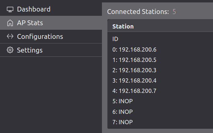
- Check AP Stats tab to see connected stations
- Note the IP addresses assigned to each STA
Manual Configuration (if needed)
Section titled “Manual Configuration (if needed)”- Access each STA’s web interface at
http://192.168.200.xWhere x is the station’s IP last octet.
Configure STA settings:
- Wi-Fi Mode: Station (STA)
- SSID: Same as AP (
3DR_xxxxxx) - Security: Same as AP
- Channel Frequency: Same as AP
Save and reboot for each STA
Step 4: Verify Communication
Section titled “Step 4: Verify Communication”Test AP-STA Communication
Section titled “Test AP-STA Communication”- Check AP Stats tab:
- All STAs should show as “Connected”
- Note their IP addresses
- Check signal strength indicators
- Test data flow:
- Send MAVLink data from your autopilot
- Verify it appears at the AP
- Check for any error messages
Test End-to-End Communication
Section titled “Test End-to-End Communication”- Configure your ground station to connect to the AP
- Verify telemetry data flows from drone to ground station
- Test command sending from ground station to drone
Advanced Configuration
Section titled “Advanced Configuration”Network Optimization
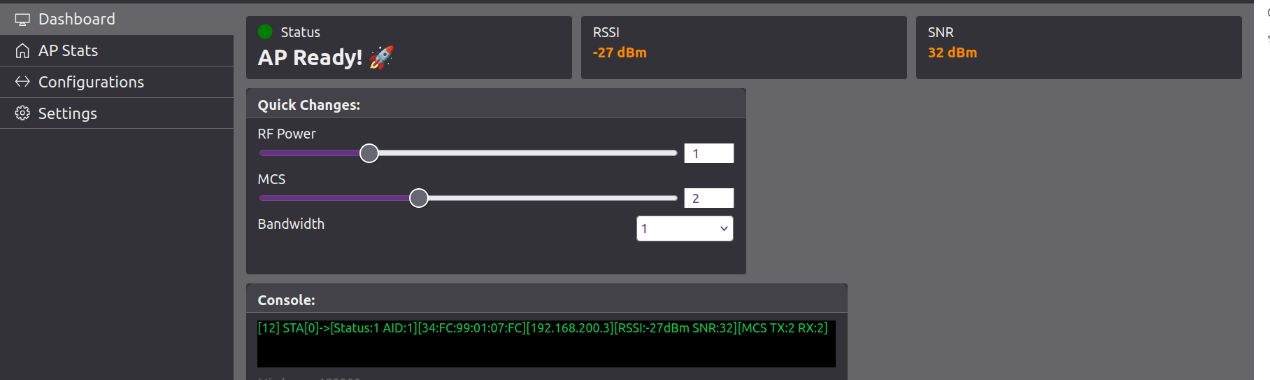
Section titled “Network Optimization”- Power Settings
- TX Power: Adjust based on range requirements
- Higher power = longer range, more battery usage
- Lower power = shorter range, less battery usage
- Channel Selection
- US (FCC): 902-928 MHz range
- Europe: 863-868 MHz range
- Choose channels with the least interference in your area
Security Configuration
Section titled “Security Configuration”WPA2 Setup
- Set a strong password (minimum 8 characters)
- Use WPA2-PSK for better security
- Avoid WEP (deprecated and insecure)
Network Isolation
- Enable client isolation if you don’t want STAs to communicate with each other
- Use VLANs for enterprise deployments
Mesh Network Setup
Section titled “Mesh Network Setup”Tree-based Mesh
Section titled “Tree-based Mesh”Update firmware to mesh-capable version
Configure mesh parameters:
- Mesh ID
- Parent selection criteria
- Routing protocols
Deploy modules in tree topology
Test mesh connectivity between all nodes
Firmware Updates
Section titled “Firmware Updates”Prerequisites
- All modules powered on and connected
- Firmware files for both AP and STA modules
- Stable network connection
Step 1: Update STA Modules First
Section titled “Step 1: Update STA Modules First”For each STA module:
- Access web interface:
http://192.168.200.x - Go to Settings > Firmware Update
- Upload STA firmware file
- Wait for reboot and reconnection
- Access web interface:
Verify all STAs reconnect to the AP
Step 2: Update AP Module
Section titled “Step 2: Update AP Module”- Access AP interface:
http://192.168.200.1 - Go to Settings > Firmware Update
- Upload AP firmware file
- Wait for AP reboot (network will be temporarily unavailable)
Step 3: Verify Update Success
Section titled “Step 3: Verify Update Success”- Check all modules are running new firmware
- Test communication between all modules
- Verify web interfaces load correctly
Troubleshooting
Section titled “Troubleshooting”STA Not Connecting
Section titled “STA Not Connecting”Symptoms: STA doesn’t appear in AP Stats
Solutions:
- Check power and connections
- Verify SSID and security settings match AP
- Wait 2-3 minutes for automatic connection
- Power cycle the STA module
Poor Signal Strength
Section titled “Poor Signal Strength”Symptoms: Low signal bars, intermittent connection
Solutions:
- Increase TX power on both AP and STA
- Check for physical obstructions
- Try different channel frequency
- Reposition modules for better line-of-sight
Web Interface Not Loading
Section titled “Web Interface Not Loading”Symptoms: Can’t access configuration pages
Solutions:
- Clear browser cache and cookies
- Try different browser
- Check network connection settings
- Verify correct IP address
Firmware Update Fails
Section titled “Firmware Update Fails”Symptoms: Upload fails or module becomes unresponsive
Solutions:
- Verify correct firmware file for module type
- Check file size (should be ~1MB)
- Ensure stable network during upload
- Power cycle and try again
Recovery Procedures
Section titled “Recovery Procedures”If AP Becomes Unresponsive:
- Power cycle the AP module
- Wait 3-5 minutes for full reboot
- Try accessing
http://192.168.200.1again - Check for error messages in serial output
If STA Won’t Reconnect:
- Power cycle the STA module
- Wait 2-3 minutes for reconnection
- Check AP Stats to see if it appears
- Reconfigure if necessary
If Wrong Firmware Uploaded:
- Use direct Ethernet connection to access the device
- Reconfigure WiFi settings through web interface
- Upload correct firmware for the module type
Best Practices
Section titled “Best Practices”Installation Tips
Section titled “Installation Tips”- Mount modules away from metal objects and antennas
- Use quality cables for power and data connections
- Secure connections to prevent vibration damage
- Test thoroughly before flight operations
Network Planning
Section titled “Network Planning”- Plan your network topology before deployment
- Consider range requirements vs. power consumption
- Test in your actual environment before critical operations
- Have backup modules ready for critical applications
Maintenance
Section titled “Maintenance”- Regular firmware updates for security and features
- Monitor signal strength and connection quality
- Check for physical damage after rough landings
- Keep configuration backups for quick recovery
QGroundControl how-to
Section titled “QGroundControl how-to”Follow these steps to connect your 3DR Radio 2 to QGroundControl (QGC):
1. Connect the AP Module to Your Host PC
Section titled “1. Connect the AP Module to Your Host PC”- Power up the AP (Access Point) module and connect it to your host PC via Ethernet or WiFi.
- Ensure your PC joins the same IP subnet as the AP (e.g.,
192.168.200.250).- On Linux, you can verify your connection with
ip addrorifconfig.
- On Linux, you can verify your connection with
- Confirm you can access the AP’s web interface (typically at
http://192.168.200.1).
2. Ensure STA Module is Connected to Flight Controller
Section titled “2. Ensure STA Module is Connected to Flight Controller”- The STA (Station) module should be connected to your flight controller’s UART telemetry port.
- Power up the STA module and ensure it joins the AP network.
3. Configure QGroundControl Communication Link
Section titled “3. Configure QGroundControl Communication Link”- Open QGroundControl on your host PC.
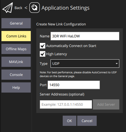
- Go to Application Settings (gear icon) → Comm Links.
- Edit the existing links or add a new link:
- You can give the link a custom name for easy identification.
- Disable all other link types (e.g., Serial, TCP, Bluetooth).
- Enable only UDP.
- Set the UDP port to
14550(default for MAVLink). - Optionally, select Automatically Connect on Start so QGroundControl connects as soon as it launches.
- If needed, you can also enable High Latency mode for long-range or low-bandwidth links.
- Save and connect.
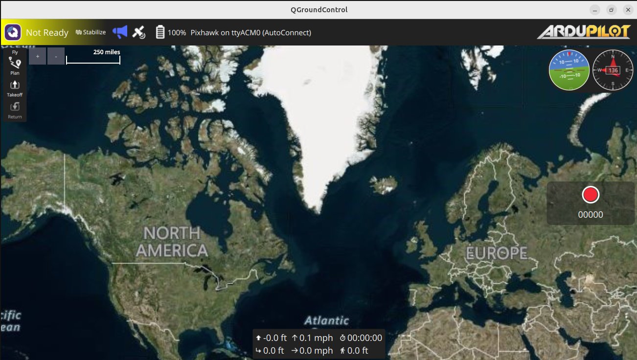
4. Verify Connection
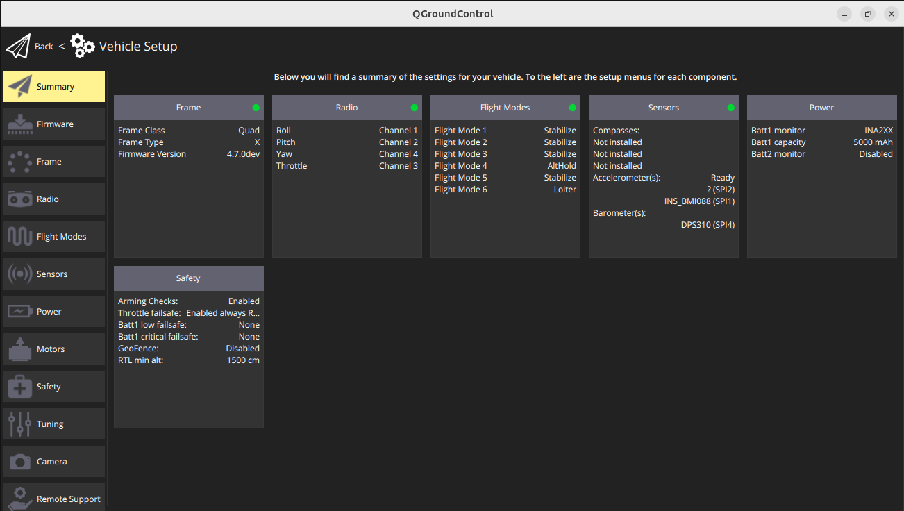
Section titled “4. Verify Connection”- QGroundControl should automatically detect the MAVLink stream from the flight controller via the HaLow link.
- You should see vehicle telemetry and status in QGC.
Version: 0.1.0 Last Updated: September 2025 Compatible with: 3DR Radio 2 R7002 v2.0 and later