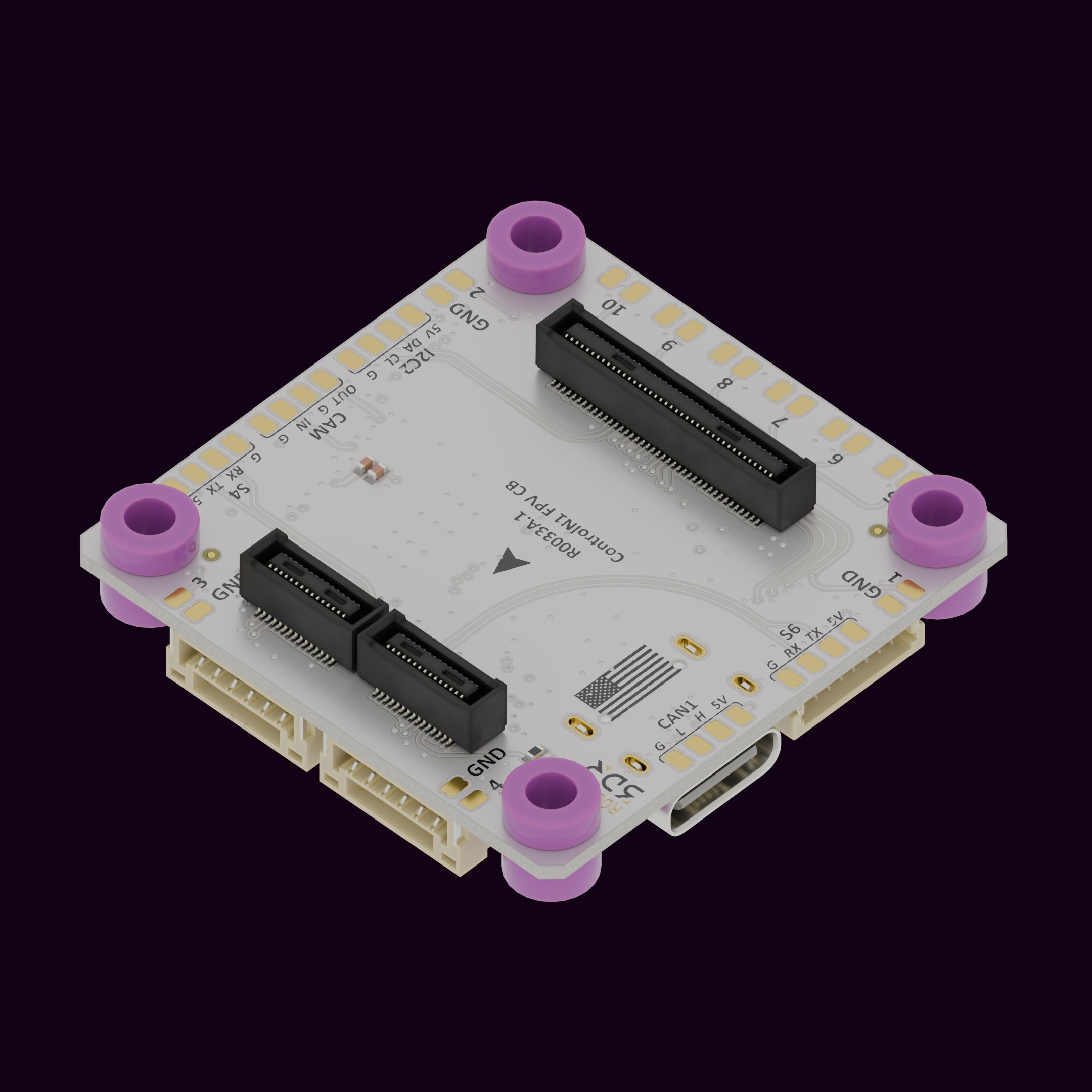
CN1 Carrier 3 - FPV
The Carrier Board 3 for the Control N1 APM (R0033) is designed for FPV platforms, with a universal form factor and onboard active components that keep the build compact and clean.
Key Features
Section titled “Key Features”- Universal Mounting Standard: Fits most FPV and DIY drone frames — sized to work with standard 4-in-1 ESC + Power Distribution Board stacks.
- Easy ESC Integration: The 8-pin JST connects directly to 4-in-1 ESC boards, reducing wiring complexity and keeping the stack tidy.
- OSD Capability: Onboard OSD outputs flight data (battery voltage, altitude, speed, distance, coordinates) to analog video transmitters.
- 5V power supply for all peripherals — no external BEC needed (6s).
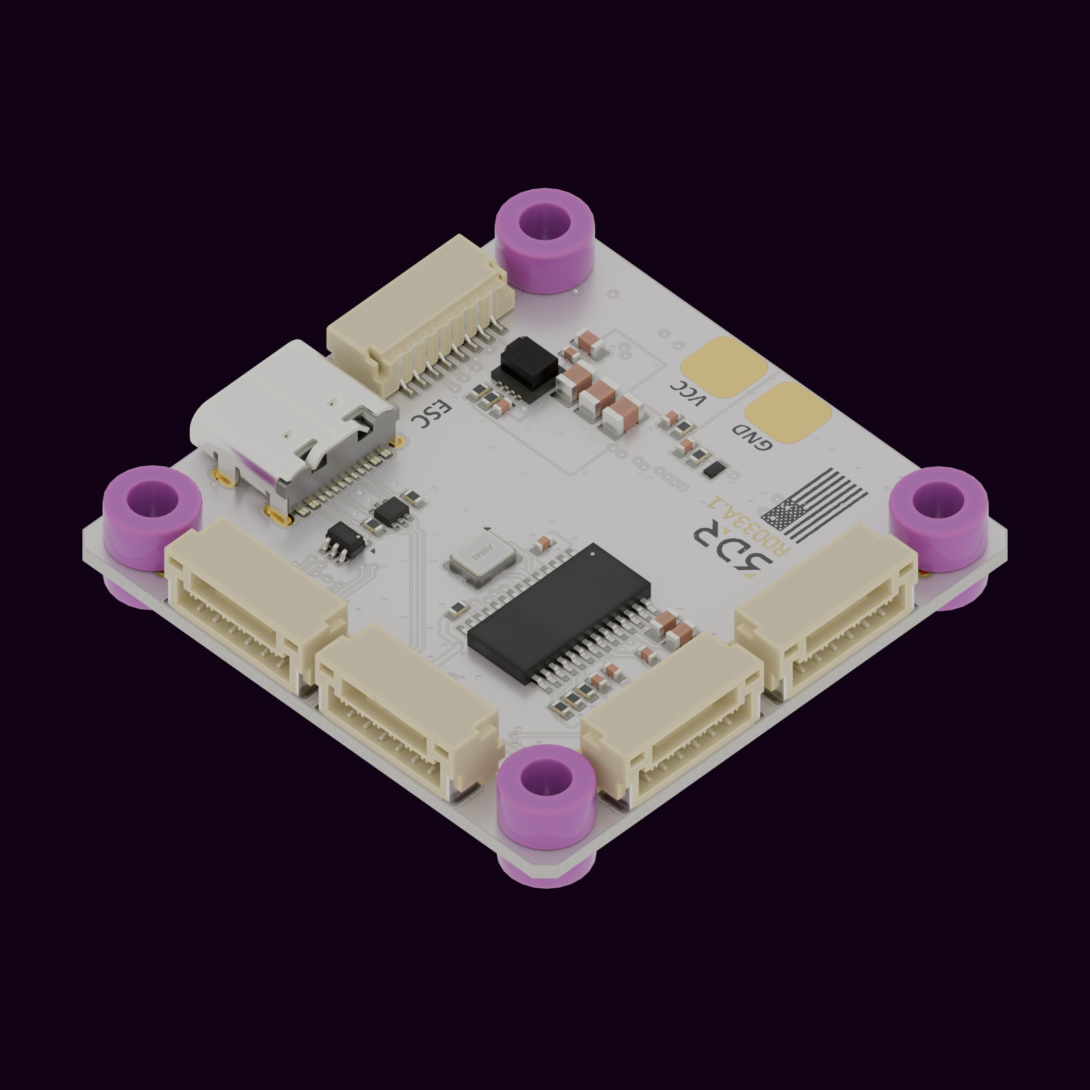
3D View
Section titled “3D View”Loading 3D model…
Use Cases
Section titled “Use Cases”- Designed for pilots who want a highly modular, do-everything FPV platform.
Installation & Setup
Section titled “Installation & Setup”- Unpack the product and inspect for any visible damage.
- Align the connector/interface with the corresponding port on Control N1 (R0024).
- Secure the connection by pressing firm and equally both boards against each other.
- Power On the base product to verify successful integration.
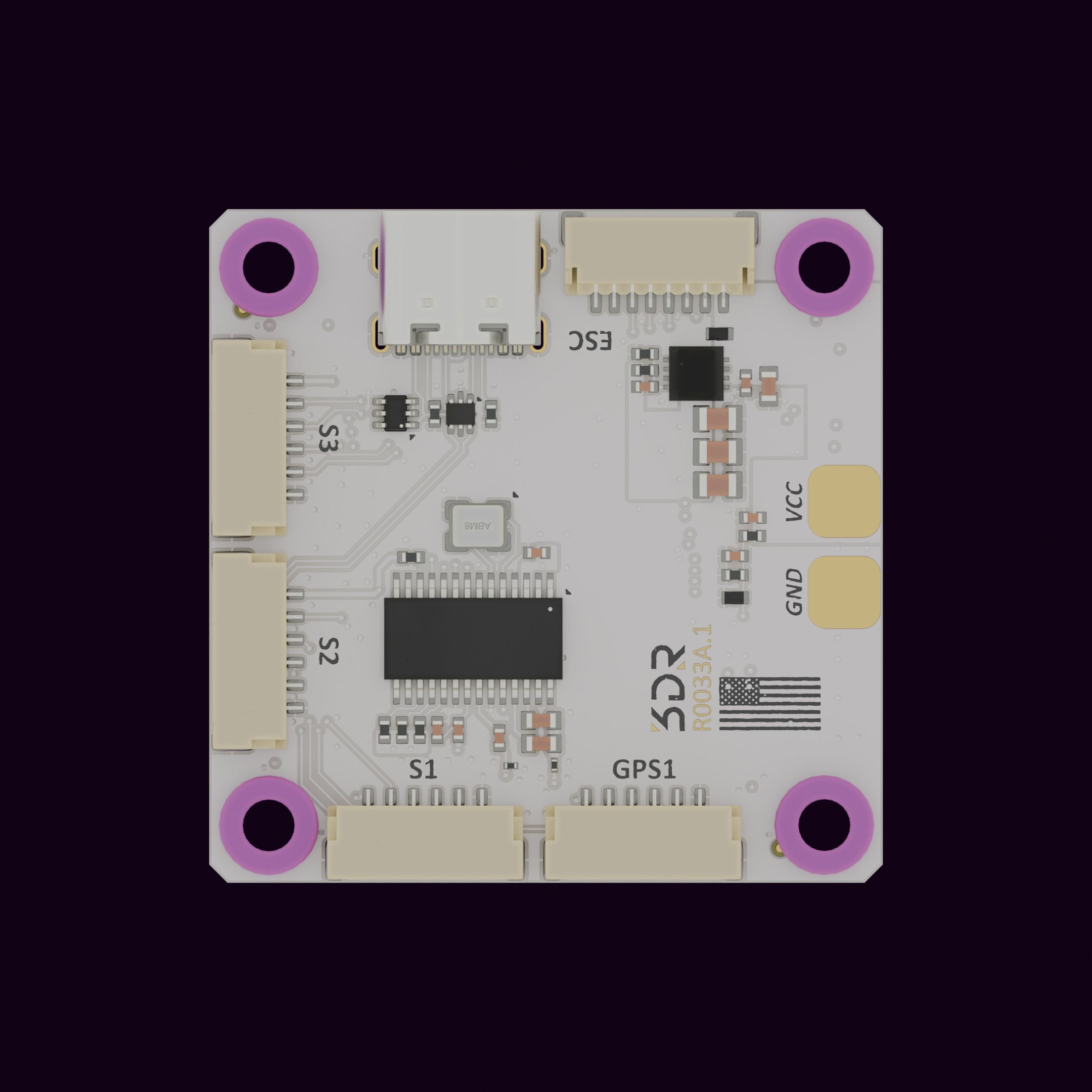
Available Ports
Section titled “Available Ports”- USB-C
- VBATT [pads]
- GPS1 (SG7 + I2C1)
- Serial 1 (SG1) w/Flow Control
- Serial 2 (SG2) w/Flow Control
- Serial 3 (SG3) w/Flow Control
- Serial 4 (SG4) [pads]
- Serial 6 (SG6) [pads]
- I2C2 (I2C2) [pads]
- CAN1 (CAN1) [pads]
- PWM (10x total — 4x motors via ESC connector or pads, 6x servos via pads)
- ESC (uses PWM channels 1–4)
All pads are labeled on the board itself.
Connector Pinouts
Section titled “Connector Pinouts”
ESC Connector Pinout
Section titled “ESC Connector Pinout”| Pin | Signal | Description |
|---|---|---|
| 1 | VCC | Battery supply |
| 2 | GND | Ground |
| 3 | CH1 | PWM |
| 4 | CH2 | PWM |
| 5 | CH3 | PWM |
| 6 | CH4 | PWM |
| 7 | NC | Not Connected |
| 8 | NC | Not Connected |
GPS1 Connector Pinout
Section titled “GPS1 Connector Pinout”| Pin | Signal | Description |
|---|---|---|
| 1 | 5V | 5V input for GPS |
| 2 | S7_TX | Serial transmit from GPS |
| 3 | S7_RX | Serial receive to GPS |
| 4 | I2C_SCL | I2C clock line |
| 5 | I2C_SDA | I2C data line |
| 6 | GND | Ground |
Serial 1, 2, 3 w/Flow Control Connector Pinouts
Section titled “Serial 1, 2, 3 w/Flow Control Connector Pinouts”| Pin | Signal | Description |
|---|---|---|
| 1 | +5V | +5V power input |
| 2 | S(1,2,3)_TX | Serial transmit (UART TX) |
| 3 | S(1,2,3)_RX | Serial receive (UART RX) |
| 4 | S(1,2,3)_CTS | Clear To Send (hardware flow control) |
| 5 | S(1,2,3)_RTS | Request To Send (hardware flow control) |
| 6 | GND | Ground |
Mechanical Information
Section titled “Mechanical Information”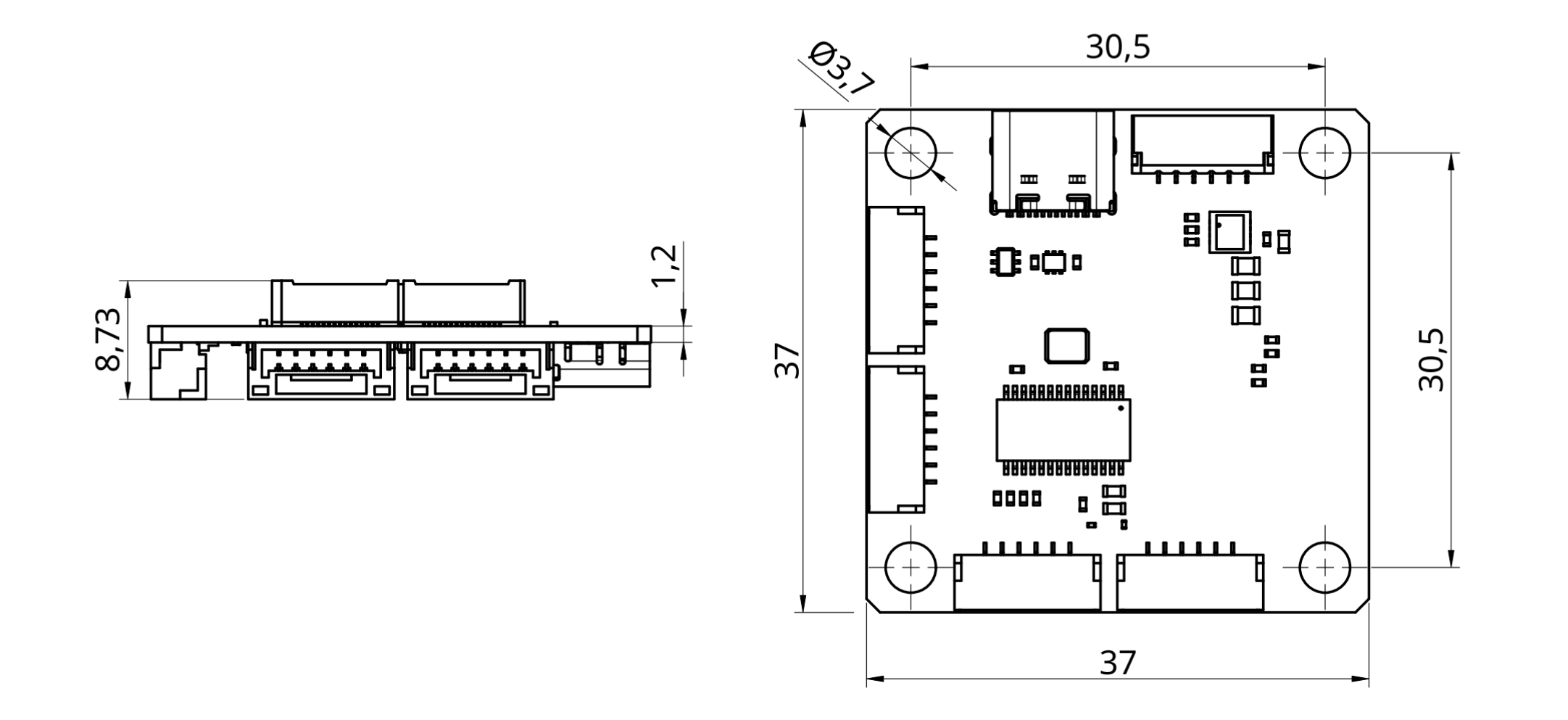
Stack height with CN1 mounted: 10.0mm
Electrical Information
Section titled “Electrical Information”| Parameter | Specification |
|---|---|
| Operating Voltage Range | 6.4V – 36V (absolute max 40V) |
| Peripheral Output Voltage | 5V at 600mA |
Do not use both power inputs simultaneously — use only one at a time.
Maintenance
Section titled “Maintenance”- Clean with a dry cloth; avoid moisture or abrasive materials.
- Periodically check connection points for wear or loosening.
- Store in a cool, dry place when not in use.
If you have further questions, contact us.